SECTION MODULUS:
- It is the ration of moment of inertia and the distance of the topmost or the bottommost fiber from the neutral axis.
Section Modulus, Z = [frac up=”I” down=”ymax“]
- It represents the strength of the section.
- Greater the value of Z, greater will be the strength of the section.
- The section modulus depends upon the moment of inertia which again depends not only on the total area of the cross-section but also on the disposition of the area with respect to neutral axis.
SECTION MODULUS OF VARIOUS SHAPES:
-
TRIANGLUAR SECTION:

Moment of Inertia at neutral axis, IN.A = [frac up=”bh3” down=”36″]
ymax = [frac up=”2h” down=”3″]
Section Modulus, ZN.A = [frac up=”IN.A” down=”ymax“] = [frac up=”bh3/36″ down=”2h/3″] = [frac up=”bh2” down=”24″]
-
SQUARE SECTION (Horizontal and Vertical Sides):
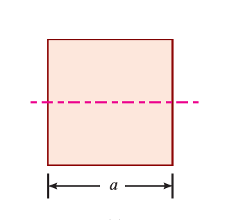
Area, A = a2
Moment of Inertia, IN.A = [frac up=”a4” down=”12″]
ymax = [frac up=”a” down=”2″]
Section Modulus, ZN.A = [frac up=”a4/12″ down=”a/2″] = [frac up=”a3” down=”6″]
-
SQUARE SECTION (Horizontal and Vertical Diagonals):

Area, A = a2
Moment of Inertia, IN.A = [frac up=”a4” down=”12″]
ymax = [frac up=”a” down=”√2″]
Section Modulus, ZN.A = [frac up=”a4/12″ down=”a/√2″] = [frac up=”a3” down=”6√2″]
- For axial loading, square with horizontal and vertical sides are equally strong.
- For bending stress, square with horizontal and vertical diagonals is stronger than square with horizontal and vertical sides because its section modulus is more.
- A square cross-section with horizontal and vertical sides is 41.4% stronger than square cross-section with horizontal and vertical diagonals.
-
RECTANGULAR SECTION:
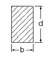
Moment of Inertia at neutral axis, IN.A = [frac up=”bd3” down=”12″]
ymax = [frac up=”d” down=”2″]
Section Modulus, ZN.A = [frac up=”IN.A” down=”ymax“] = [frac up=”bd3/12″ down=”d/2″] = [frac up=”bd2” down=”6″]
-
CIRCULAR SECTION:
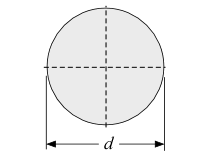
Moment of Inertia at neutral axis, IN.A = [frac up=”πd4” down=”64″]
ymax = [frac up=”d” down=”2″]
Section Modulus, ZN.A = [frac up=”IN.A” down=”ymax“] = [frac up=”πd4/64″ down=”d/2″] = [frac up=”πd3” down=”32″]
BEAM OF UNIFORM STRENGTH:
- A beam is said to be a beam of uniform strength when bending stress developed at each and every cross-section of the beam remains same.
- The beam of constant cross-section throughout the length has constant section modulus and has constant or uniform moment of resistance. But in actual practice, the moment generally varies along the length and in that case such a section is not economical. Under heavy loads, a beam of variable section is designed to have uniform strength.
- In presence of Transverse Shear Load every prismatic beam is a beam of non-uniform strength due to variable bending moment.
- In presence of Transverse Shear Load to obtain a beam of uniform strength non-prismatic beams are used.
- Non-prismatic beams can be obtained by the following two methods:
-
- By varying width and keeping depth as constant.
- By varying depth and keeping width as constant.
-
Method 1: VARYING WIDTH AND KEEPING DEPTH AS CONSTANT
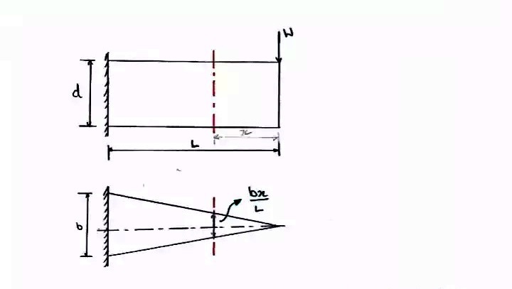
Consider a cantilever beam of uniform strength on which a load of W newton is acting at the end.
For beam of uniform strength,
Bending stress at section x-x = Bending stress at free end
(σb)x-x = (σb)L-L
[frac up=”Mx-x” down=”Zx-x“] = [frac up=”ML-L” down=”ZL-L“]
[frac up=”W . x” down=”bx . d2/6″] = [frac up=”W . L” down=”b . d2/6″]
[frac up=”x” down=”bx“] = [frac up=”L” down=”b”]
bx = b [frac up=”x” down=”L”]
METHOD 2: VARYING DEPTH AND KEEPING WIDTH AS CONSTANT:
Bending stress at section x-x = Bending stress at free end
(σb)x-x = (σb)L-L
[frac up=”Mx-x” down=”Zx-x“] = [frac up=”ML-L” down=”ZL-L“]
[frac up=”W . x” down=”b . dx2/6″] = [frac up=”W . L” down=”b . d2/6″]
[frac up=”x” down=”(dx)2“] = [frac up=”L” down=”d2“]
dx = d √[frac up=”x” down=”L”]
BEAM OF COMPOSITE SECTION (FLITCHED BEAM):
- Beams that are made of more than one material are called composite beams. e.g. Bimetallic beams, Sandwich beams, Flitched beams, Reinforced concrete beams.
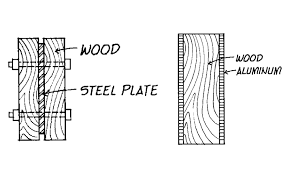
- These beams can be analyzed by the same bending theory because the assumption that cross-section that are plane before bending remain plane after bending is valid in pure bending regardless of the material.
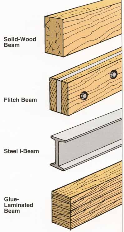
- The strain distribution along the depth of the beam is linear. However, such structures are statically indeterminate and the position of the neutral axis is not the centroid of the section. The criterion of the strain compatibility has to be used i.e. strain in the two materials, at a given vertical distance from the neutral axis has to be the same.
For More Information:- CLICK HERE
