ENGINEERING DRAWING LINES
CONVENTIONAL LINES
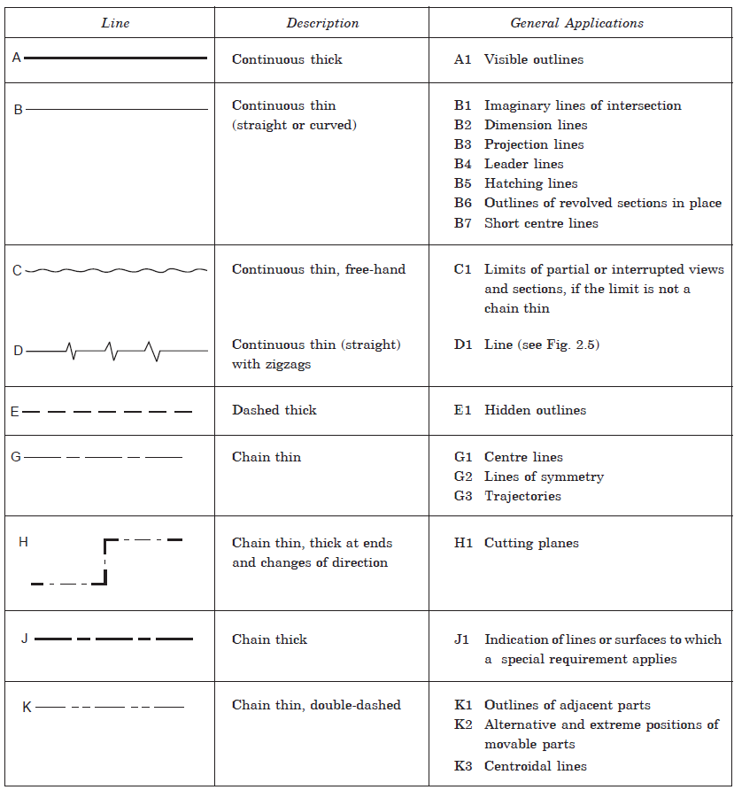
Drawings are made up of different types of lines (engineering drawing lines). Just as language with alphabets and grammar. As the basis of engineering drawing is a line, a set of conventional symbols representing all the lines needed for different purposes may well be called an alphabet of lines. Each line, in a well executed drawing has a specific meaning and function.
Lines of different thickness and features are used for specific use.
Technical drawings are drawn with different types of lines. By proper choice and application of lines product features can be correctly defined in a drawing.

These lines differ from each other in two respects:
- Their thickness or weight, e.g. thick, medium and thin.
- Their shape or construction, depending upon their conventional use.
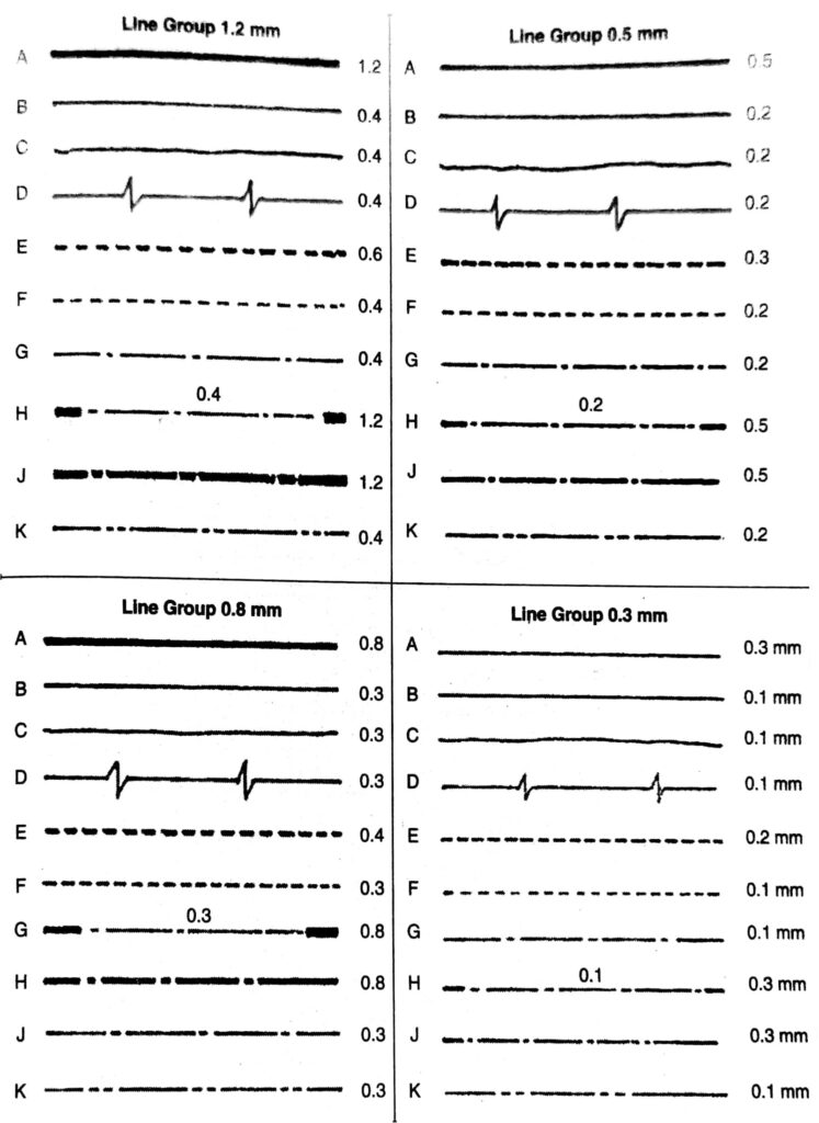
Lines specified thick should be about 3 times as thick and lines specified medium should be 1.5 times as thick as lines specified thin. The line group used on a drawing is identified from the thickest lines, i.e. visible outlines. The line group used depends upon the size of the drawing and should be chosen from one of the line groups.
THICKNESS OF LINES:

SP: 46-1988 recommends that two thickness of lines be used. In general, the ratio of the thick to the thin line should not be less than 2:1. Grading of lines is in √2 increments. The thickness of lines should be chosen, according to the size and the type of drawing, from the following:
0.18, 0.25, 0.35, 0.5, 0.7, 1, 1.4 and 2 mm.
For all views of one piece to the same scale, the thickness of the lines should be the same. Owing to difficulties in methods of reduction, the line thickness of 0.18 mm should be avoided. The minimum space between parallel lines, including hatching, should never be less than twice the thickness of heaviest line. It is further recommended that these spaces should never be less than 0.7 mm.
VISIBLE OUTLINE OR OBJECT LINE:
Outline is the outstanding feature in any drawing. These are thick continuous lines and are used to represent the outline or overall shape of an object. Every edge or surface that is visible is represented by these lines.
SECTION LINES:
These are thin continuous lines, uniformly spaced and are used to show a part in section. These lines are usually drawn at an angle of 45° (may be 60° or 30°) to the horizontal. These lines extend edge to edge of the surface in which these are drawn.
CONSTRUCTION LINES:
These are thin continuous lines used for projecting or transferring location from one view to the other and for constructing drawings. These lines do no appear in the finished drawings expect in geometrical drawings where these are usually not removed. These are not drawn in ink.
HIDDEN LINES:
Shape which can not be seen, when an object is looked at from an outside viewing position, can be drawn in hidden detail. It is not necessary to include all hidden detail in views in a drawing. Only sufficient of the hidden detail need to be included to show quite clearly the exact shape of the object. Hidden lines may be omitted, when not required, to preserve the clarity of the drawing. When adding hidden detail lines to a drawing, the following rules should be followed:
- Hidden detail lines are medium thick lines consisting of short dashes, about 3 mm long with gaps of nearly half their length between them. The length of the dashes varies slightly in relationship to the size of the drawing.
- Hidden detail lines forming angles should be drawn with dashes touching at the angle.
- In a hidden detail, if a line meets a curved line, a dash should touch at the point of tangency.
- When hidden detail lines cross visible outlines either a dash should clearly cross the outline or dashes should be drawn with a gap on each side of the visible outline. Unless this rule is observed, the hidden detail would show that the detail drawn commences at the visible outline. These are represented by evenly spaced short and uniform dashes, used to represent invisible or hidden details or parts on drawings. These dashes are about 60% thinner than the object lines.
CENTRE LINES, LOCUS LINES,
EXTREME POSITION OF MOVABLE PARTS, PITCH CIRLCES AND PARTS SITUATED IN FRONT OF THE CUTTING PLANE:
These thin chain lines are represented by long and short dashes. The proportion for these long and short dashes is ranging from 6:1 to 4:1. In any one drawing the proportion selected should be maintained by eye judgement.
The centre lines are used to centre the symmetrical views of circular parts, to indicate centre points, axes of symmetrical parts, axes of symmetry and also for giving the location dimensions. These lines are first to be drawn in any drawing after carefully spacing the various views to be drawn. Following points need special care when drawing center lines:
- Where two centre line cross, the short dashes should intersect symmetrically.
- When a centre line coincides with either a visible or a hidden line, it should not be continued into such a line.
- No centre line should begin or end at the lines representing surfaces of the object, but should extend about 5 mm beyond such surfaces.
- Centre lines should be drawn for all parts, visible or hidden, which have these lines.
- Centre lines should begin and end with a long dash.
- Centre lines should not be used as dimensions lines for the purpose of dimensioning but may be extended for the purpose of dimensioning.
- Centre lines should extend for a short distance beyond the feature unless they are required for dimensioning or some other purpose.
- If an angle is formed by chain lines, then the long dashes should intersect and define the angle.
Locus lies are particularly used to show the paths traced out by any one point under given conditions.
DIMENSION LINES:
These are continuous thin lines.
EXTENSION LINES:
These are continuous thin lines.
OUTLINES OF REVOLVED SECTIONS AND ADJACENT PARTS:
These are continuous thin lines.
CUTTING PLANE LINES:
These lines are made up of alternately a long dash and a short dash in the ratio of about 6:1 to 4:1 and are drawn as centre lines but are extra thick at the ends and having arrows touching them. These are used to show the edge of the cutting plane when an object is being sectioned to show the hidden details. The arrows, attached to the ends of such lines indicate the direction in which the section is to be seen.
BREAK LINES:
- SHORT BREAKS AND IRREGULAR BOUNDARY LINES:
These are continuous thin lines drawn freehand and are used to show a break of an object which extends over a short length of drawing or to indicate the irregular boundary of an object. These result in a saving in space and time used for drawing without loss of detail.
- LONG BREAKS:
These are continuous thin ruled lines having freehand zigzags at suitable intervals and are used when the brake extend over a considerable length of the drawing.
LONG CHAIN THICK LINES:
These are composed of alternate long and short dashes and it is used to indicate surfaces which are to receive additional treatment.
RELATED VIDEOS FOR ENGINEERING DRAWING LINES:
