ARRANGEMENT AND INDICATION OF DIMENSIONS:
The arrangement of dimensioning on a drawing shall indicate clearly the design purpose.
The arrangements of dimensions are:
- Chain Dimensioning
- Dimensioning from a common feature
- Dimensioning by co-ordinates
- Combined dimensioning
CHAIN DIMENSIONING:
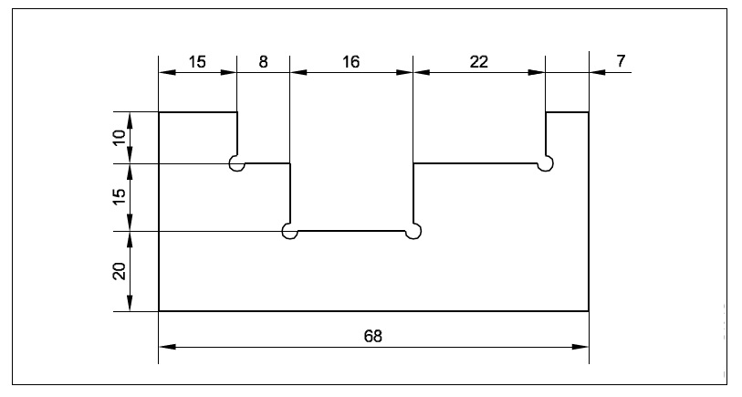
It is used where the possible accumulation of tolerances does not infringe (effect) on the functional requirement of the component.
DIMENSIONING FROM A COMMON FEATURE:
This feature is used where a number of dimensions of the same direction relate to a common origin.
It may be executed as parallel dimensioning or as superimposed running dimensioning.
PARALLEL DIMENSIONING:
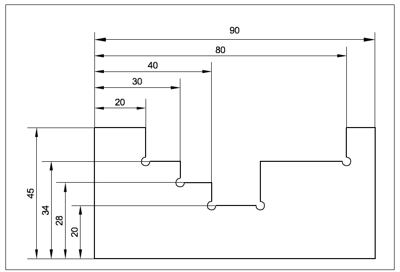
Dimensions of features are taken from one datum/common origin and are shown parallel to other and placed, so that the dimensional values can easily be added.
SUPERIMPOSED RUNNING (PROGRESSIVE) DIMENSIONING:
It is a simplified dimensioning also Cumulative error is controlled. It starts from one origin with arrow heads in one direction only. This may be used where there are space limitations and where no legibility problems would occur.
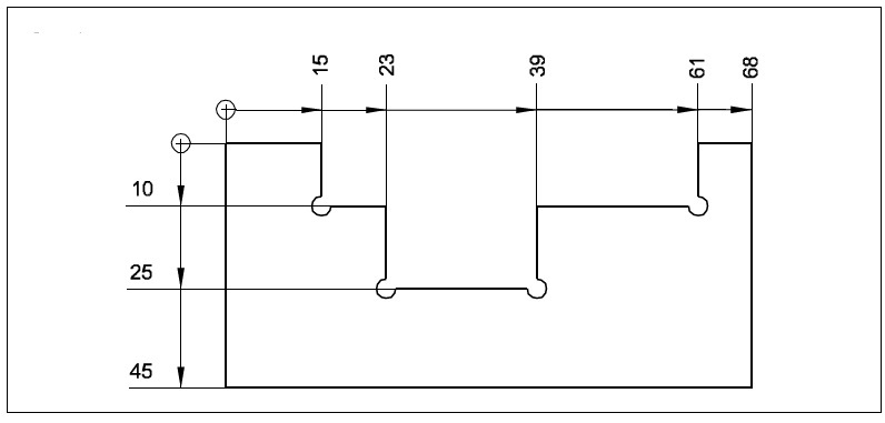
The origin indication is placed appropriately and the opposite ends of each dimension line shall be terminated only with an arrow head. It may be advantageous to use superimposed running dimensions in two directions.
DIMENSIONING BY CO-ORDINATES:
This system is much used for components, produced on jig boring machine. Two edges are taken as datum. (references)
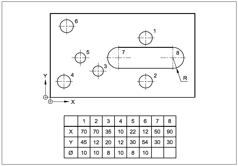
This method is useful in indicating places/positions in country, city and site plans.
COMBINED DIMENSIONING:
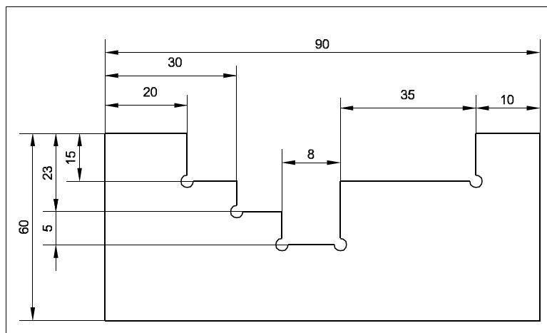
In this method, dimensions are given in chain and parallel dimensioning. Common feature is combined.
METHODS OF DIMENSIONING COMMON FEATURES:
DIMENSIONING TAPERED PARTS:
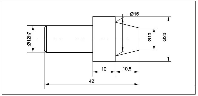
When tapered part is dimensioned then extension lines be at an angle and parallel to each other. Dimension line be drawn parallel to the feature to be dimensioned.
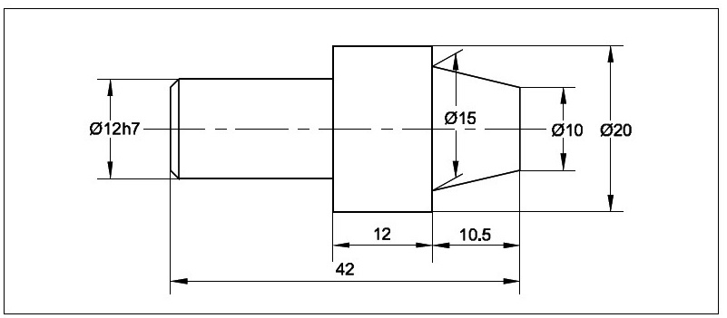
DIMENSIONING SMALLER WIDTH:
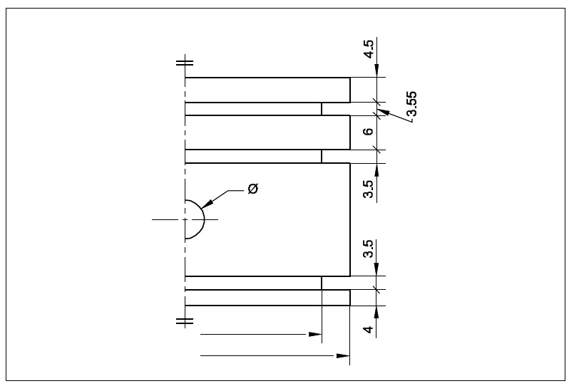
Arrow heads are replaced by oblique lines. To avoid placing dimensions too far away from feature,
dimension lines are drawn closer and not fully.
DIMENSIONING CYLINDRICAL AND SPHERICAL FEATURES:
Cylindrical features have diameter and length whereas sphere has a diameter only.

Diameter may be indicated by any one of the abbreviation D, Dia, d, dia or φ and radius may be indicated by R, r, Rad or rad by square. Any one abbreviation or symbol on a drawing may be indicated by SQ or .
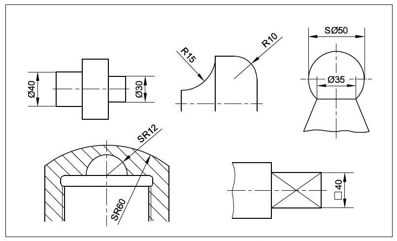
The length if any required to give along with dia, if it is shown as φ…x… long.
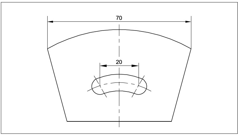
DIMENSIONING A CHORD:
Chord is dimensioned as shown in the figure.
DIMENSIONING AN ARC OR RADIUS:
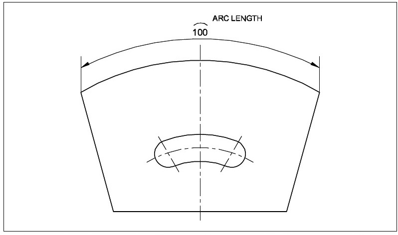
A small arc is shown over the dimension value, while dimensioning an arc.
DIMENSIONING EQUIDISTANT FEATURES:
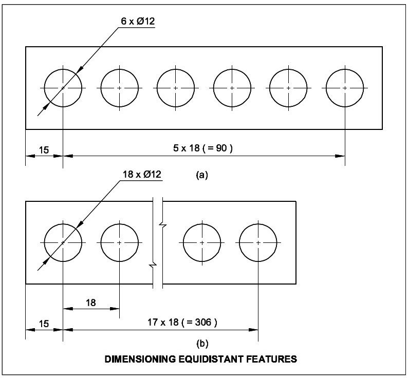
Where equidistant features or uniformly arranged elements are parts of the drawing, specification of the dimensions may be simplified.
DIMENSIONING ANGLES AND ANGULAR SPACING:
Equal angles eg. 4 x 10° = 40°
Equal centre distances eg. 4 x 10 = 40.
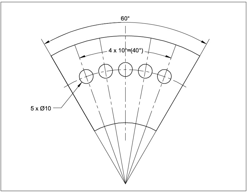
When the drawing is clear, symbols or abbreviation viz. dia, PCD and angle can be omitted.
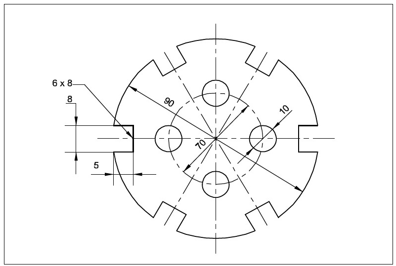
DIMENSIONING PERIPHERY:
Periphery is dimensioned as shown in the figure.
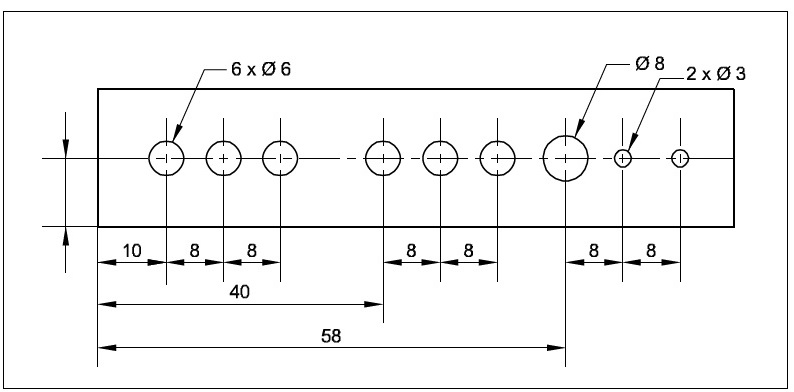
DIMENSIONING REPEATED FEATURES:
When elements of same size occur, but not of same pitch.
COUNTERSINKS AND COUNTER-BORES:
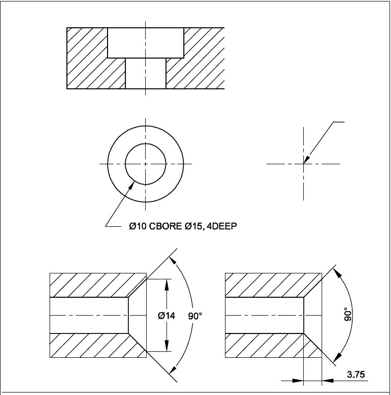
For simplification, the holes are indicated by centre lines and marked by different letters to different type/size of hole. The holes maybe plain, through blind, tapped, countersink of counter bored.
DIMENSIONING CHAMFERS AND UNDERCUTS:
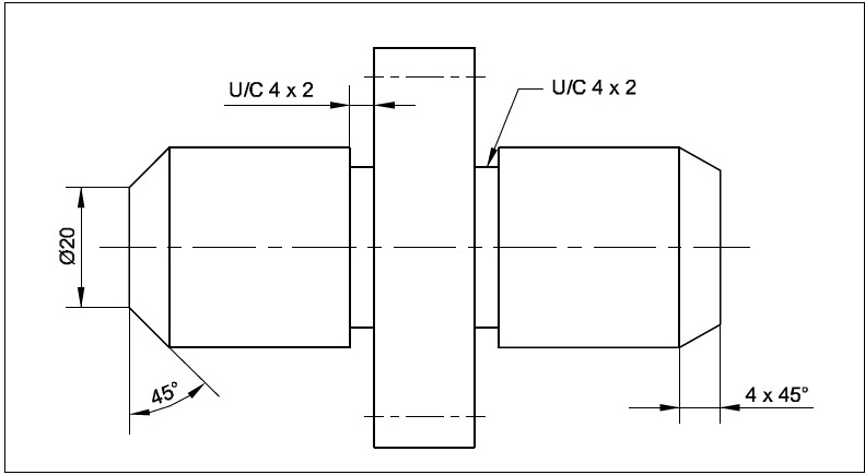
Chamfer of 45° may be shown by leader line indicating chamfer width and angle or by dimension line with chamfer width and angle.
DIMENSIONING UNDERCUT:
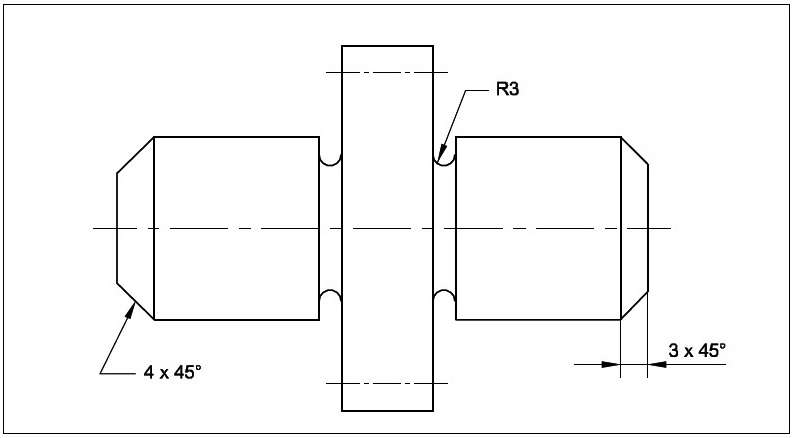
Undercuts are dimensioned either by normal dimensioning the width i.e. u/ c 4 x 2 or by leader terminating horizontally u/c 4 x 2.
PRINCIPLES AND APPLICATION OF DIMENSIONING:
Before proceeding to give dimensions, consider the following steps:
- Mentally visualize the object and divide it into geometrical shapes such as prisms, cones, cylinders, pyramids etc.
- Place the size dimension on each form.
- Consider the relationship of mating parts and the process of production, then select the locating (reference or datum) centre lines and surfaces.
- Ensure that each geometrical form is located from a centre line and/or a finished surface.
- Place the overall dimensions.
- Add the necessary notes like surface finish, specific operations, material, fit, type of thread etc.
- All dimensional information necessary to define a part or component clearly and completely shall be shown directly on a drawing unless this information is specified in relevant documents.
- Each feature shall be dimensioned once only on a drawing.
- Dimension shall be placed on the view or section that most clearly shows the features.
- Each drawing shall use the same unit (for example, millimeters) for all dimensions but without showing the unit symbol. In order to avoid misinterpretation, the pre-dominant unit symbol on a drawing may be specified in a note.
- Where other units have to be shown as part of the drawing specification ( for example, N, m for torque or kPa for pressure), the appropriate unit symbol shall be shown with the value.
- No more dimensions than are necessary to define a part or an end product shall be shown on a drawing. No feature of a part or an end product shall be defined by more than one dimension in any one direction. Exception may, however be made
- Where it is necessary to give additional dimensions at intermediate stages of production (for example, the size of a feature prior to carburizing and finishing).
- Where the addition of an auxiliary dimension would be advantageous.
- Production processes or inspection methods should not be specified unless they are essential to ensure satisfactory functioning or interchangeability.
- Functional dimensions should be shown directly on the drawing wherever possible.
- The non-functional dimensions should be placed in a way which is most convenient for production and inspection.
- Projection lines should be drawn perpendicular to the feature being dimensioned. Where necessary, however, they may be drawn obliquely, but parallel to each other.
- Avoid intersection of projection lines and dimension lines, where unavoidable neither line shall be shown with a break.
- A centre line or the outline of a part shall not be used as a dimension line but may be used in place of a projection line.
- Any one style of arrow head termination shall be used on a single drawing. However, where space is too small for arrow head, oblique stroke or dot may be substituted.
RELATED VIDEOS:
