IMPORTANCE OF DIMENSIONING:
Any Component or product manufactured should be confirm to its specification. In fact, without specification of product, there cannot be production. In engineering industry, all manufacturing is controlled by the technical specification of product or components i.e. dimensions.
Technical specification provides complete information on the shape, size, tolerance, finish, material and other technical aspects such as heat treatment, surface coating and other relevant information required to manufacture a component. In most cases technical specifications of components are given in the form of a technical drawing while shape is described by various types of views i.e. Orthographic, pictorial and perspective projection and size is given by dimensions.
Dimension:
It is a numerical value expressed appropriate unit of measurement and indicated graphically on technical drawings with lines, symbols and notes.
Size dimensions:
Give the size of a component, part, hole, slot, depth, width, radius etc.
eg: L1, L3, H, h1, S etc.
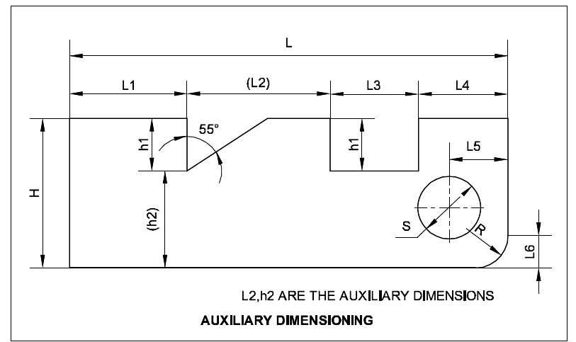
Location dimensions:
Give or fixes the relationship of the features. viz centre of holes, slots and any significant forms.
eg: L4, L5, L6
Feature:
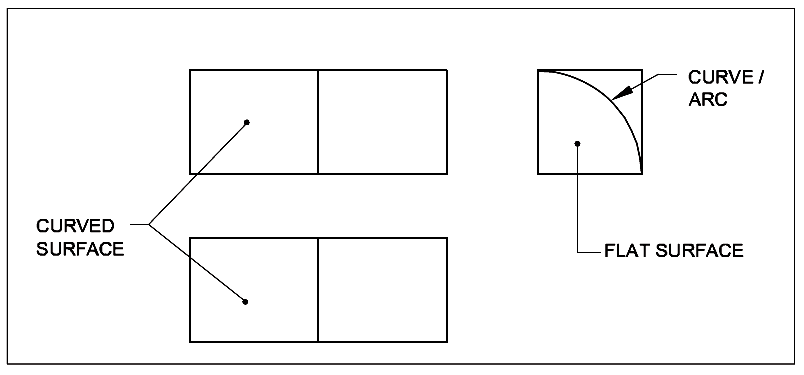
It is an individual characteristic such as flat surface. Cylindrical surface, shoulder, screw thread, a slot, a curve or profile etc.
End product:
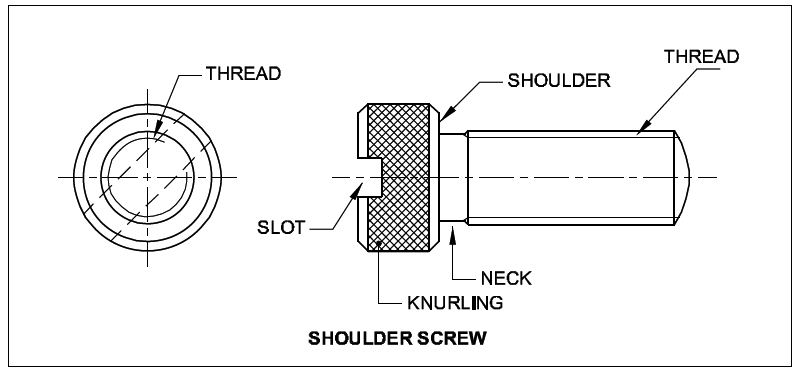
It is a part ready for direct use or assembly or it can be a part ready for further process. e.g. a casting, shoulder screw etc.
Dimensions are classified according to the following types:
Functional dimension (F):
It is a dimension which is essential to the function of the component or space. They are generally shown with limits.
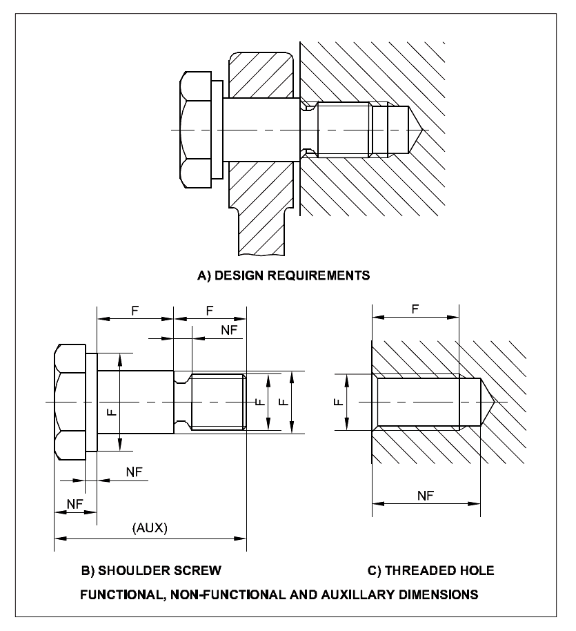
Non-functional dimension (NF):
It is a dimension which is not essential for the function of the component or space.
Auxiliary or Reference dimension (AUX/REF):
It is the dimension given for information only. It is derived from the values given on the drawing or related documents and it does not given in the production or inspection.
ELEMENTS OF DIMENSIONING:
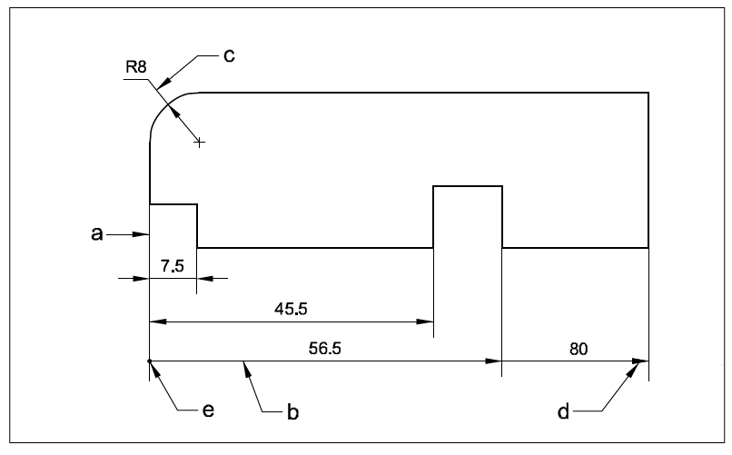
- Extension Line – a
- Dimension Line – b
- Leader Line – c
- Termination of dimension line – d
EXTENSION LINE:
It is a thin line projecting from the feature and extending beyond the dimension line.
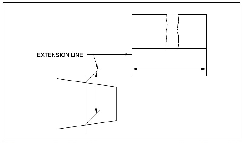
It is normally perpendicular to the feature being dimensioned, but may be drawn obliquely as shown for dimensioning tapers, parallel to each other.
Extension lines (Projection lines) should not cross the dimension lines, but where not possible the lines should not break.
DIMENSION LINE:
These are thin continuous lines, terminated at ends by arrow heads, dots or oblique lines touching the extension line.
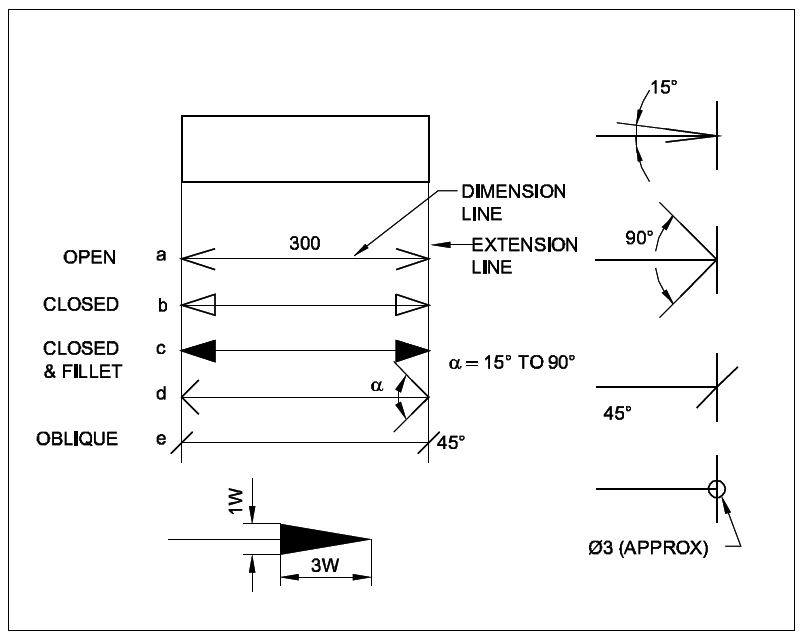
Dimension line may cut or cross another dimension line where there is no other way.
Dimension to the hidden lines be avoided.
Arrow heads may be placed outside where space is insufficient.
LEADER LINE:
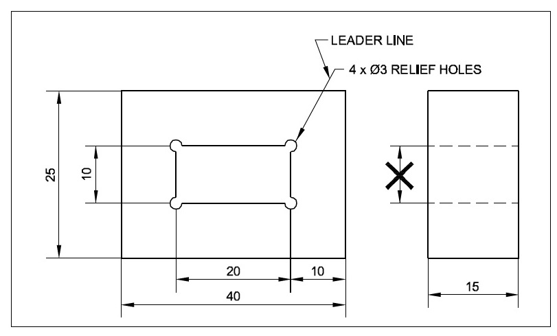
It is a thin continuous line. It connects a note or dimension with the features to which it applies.
TERMINATION AND ORIGIN INDICATION:
The size of the terminations (arrow heads/oblique strokes) shall be proportional to the size of the drawing. Only one style of arrow head shall be used on a single drawing. However, where the space is too small for the arrow heads, it may be substituted by a dot or by an oblique line. Arrow heads are drawn as short lines forming barbs at any convenient included angle between 15° and 90°. They may be open, closed or closed and filled in. Oblique strokes drawn as short line inclined at 45°.
INDICATING DIMENSIONAL VALUES ON DRAWINGS:
Indicating dimensional values on drawings: All dimensional values shall be shown on drawings in characters of sufficient size to ensure complete legibility on the original drawings as well as on reproductions made from micro-filming. They shall be placed in such a way that they are not crossed or separated by any other line on the drawing.
SYSTEM OF DIMENSIONING (Placing Dimensions) A PREPARED DRAWING
There are two systems of placing dimensions on a prepared drawing. Only one method should be used on any one drawing.
- Aligned System
- Uni-directional system
ALIGNED SYSTEM:
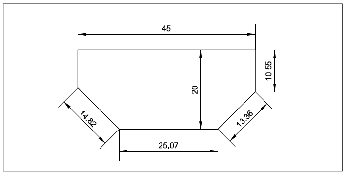
The system in which the dimensions are placed perpendicular to the dimension line. This system of placing dimensions is commonly used in engineering practice.
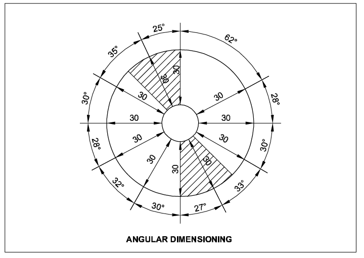
The vertical dimensions are written and read from right side. This system is commonly used for dimensioning a prepared drawing.
UNI-DIRECTIONAL SYSTEM:
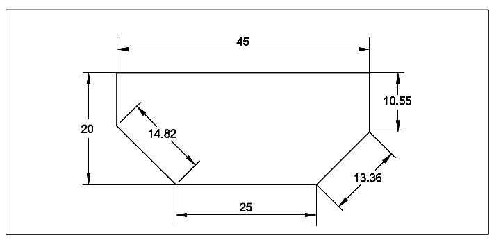
The system in which the dimensions are read always from bottom to top irrespective of direction of dimension line.
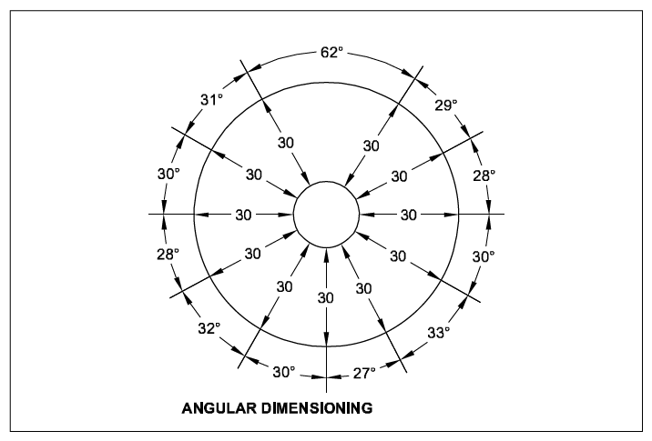
The vertical dimensions stand parallel to the dimension lines. This system is used in large drawings such as in the case of automobiles etc.
RELATED VIDEOS FOR DIMENSIONS:
