EXPERIMENT
OBJECTIVE:
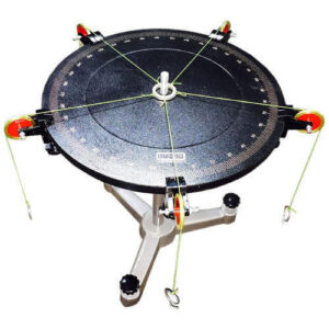
To verify the law of polygon of forces with the help of universal force table apparatus.
APPARATUS:
Universal Forces table with five pulleys, rings with five string weight, slotted weight, plain paper and geometry box.
THEORY:
Polygon law of forces states that if a number of concurrent forces are acting simultaneously on a body, are represented in magnitude and direction by the sides of a polygon, taken in order, then the resultant is represented in magnitude and direction by the closing side of the polygon, taken in opposite order.

PROCEDURE:
- Before starting the experiment make the graduated table horizontal with the help of leveling screw.
- Clamp the pulley to the graduated disc of the force table.
- Tie one and of thread to the circumference of small rings and place it around the central axis of the apparatus.
- Attach other end of the string to the weight hangs which will carry small slotted weight.
- Pass one string over each pulley.
- Place slotted weight on the weight hanger in such a manner that ring is placed around the center.
- Note down the angle between different threads and corresponding weights.
- Draw a space diagram of the force acting a part such that the time of action of each force corresponding to the angles of forces between them.
- Chose a suitable scale and make mark a point on a paper and draw the vector diagram of force system acting at a point by drawing parallel line of each force proportional to the chosen scale.
Procedure to draw vector diagram:
- Draw a line OA parallel and equal to W1 assuming a suitable scale.
- Draw a line AB parallel and equal to W2 from point A assuming the same scale.
- Similarly draw BC and CD parallel and equal to the force W3 and W4.
- Join OD i.e. the closing side by dotted line, which represents the resultant of polygon (graphically).
- Measure the line OD and compare it with W5 by using the same scale.
- Find the error by using the formula given in the observation table. Error should be positive.
OBSERVATION TABLE:
|
FORCE (in grams) |
ANGLE ( in degree) |
|||||||||||
| S. No. | W1 | W2 | W3 | W4 | W5 | θ1 | θ2 | θ3 | θ4 |
θ5 |
RESULTANT OF FORCES (R) (OD) |
ERROR IN % (W5 –R)/W5 x 100 or (R- W5)/R x 100 |
PRECAUTIONS:
- Ring should not touch the control axle of the disc and should be at the center of the table.
- Graduated disc should be made kept perfectly horizontal.
- Positions of the strings should be at the center of the table.
- Pulley should be frictionless.
RELATED VIDEOS:
