MOMENT
COUPLE:
When two equal and unlike parallel forces having different lines of action on a body, they are said to constitute a couple.
The effect of a couple acting on a rigid body is to rotate it without moving it as a whole. The movement of the whole body is not possible because the resultant force is zero in the case of forces forming a couple.

The perpendicular distance between the lines of action of two forces forming the couple is called the arm of the couple. Two equal forces of magnitude F acting at points A and B in the opposite direction form a couple with AB as arm of the couple.
The moment of a couple is known as torque which is equal to one of the force forming the couple multiplied by the arm of the couple.
Moment of a couple = F x AB = F x d
The direction and sense of couple moment are obtained by the right hand rule.

EXAMPLES:
- Winding up a clock.
- Opening or closing of a water tap.
- Moving the paddles of a bicycle.
- Opening or closing the cap of a pen.
- Steering a motor-car.
- Twisting a screw driver.
PROPERTIES:
- The algebraic sum of the moments of the forces, forming a couple, about a point in their plane is constant.
- It has no resultant force but it has resultant moment.
- Any two couples of equal moments and sense, in the same plane are equivalent in their effect.
- Two couples acting in one plane upon a rigid body, whose moments are equal but opposite in sense, balance each other.
- Any number of coplanar couples can be represented by single couple whose moment is equal to the algebraic sum of the moment of individual couples.
- A couple cannot be balanced by a single force. However, a single force can be replaced by an equal and like parallel force through any other point and couple.
ENGINEERING APPLICATIONS OF MOMENT:
There are many engineering applications of moments. Some of the important applications are:
LEVER:
A lever is a rigid bar straight or curved, which can turn about a fixed point. This fixed point is called fulcrum. The distance of the fulcrum from the load is called Resistance Arm or Load Arm. The distance of the fulcrum from the effort is called Effort Arm.
A lever works on the principle of moments i.e., when the lever is in equilibrium the algebraic sum of moments of the forces about the fulcrum is zero.
TYPES OF LEVERS:
- Simple Lever
- Cranked Lever
- Compound Lever
SIMPLE LEVER:
A simple lever is one which have only one fulcrum and have straight rigid bar. Simple lever is further classified as :
- Class I Lever:
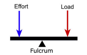
In this class of simple lever, the fulcrum always lies between load and effort.
Examples: Scissors, Weighing balance, Pliers etc.
- Class II Lever:
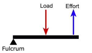
In this class of lever, load is provided between effort and column.
Examples: Nut crackers, Staplers, Bottle openers, Nail clippers etc.
- Class III Lever:
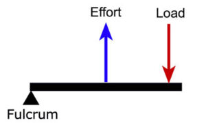
In this class of lever, load is provided between effort and column.
Examples: Safety valves, Shovels, Fishing rods, Ice tongs etc.
CRANKED LEVER:
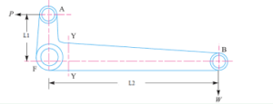
Cranked levers are made up of bent bars instead of straight bars to apply effort in any convenient direction.
COMPOUND LEVER:
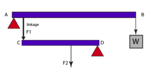
A compound lever is combination of simple levers and has more than one fulcrum. It is used to lift a heavier load with minimum effort. In compound lever we get more leverage than simple lever.
RELATED VIDEOS:
