ELASTIC CONSTANTS
Following are the characteristics of Elastic Constants:
- These are the factors which determine the deformations produced by a given stress systems.
- These are used to determine the strain theoretically.
- These are used to obtain relation between stress and strain.
- These are constant within the limits for which Hooke’s laws are obeyed.
- Various elastic constants are:
- Modulus of Elasticity (E)
-
- Poisson Ratio (μ)
-
- Modulus of Rigidity (G)
-
- Bulk Modulus (K)
- For a homogenous and isotropic material the number of Elastic Constants are 4 i.e. E, G, K, μ.
- For a homogenous and isotropic material the number of independent Elastic Constants are 2 i.e. E and M.
|
MATERIAL |
INDEPENDENT ELASTIC CONSTANT |
|
Isotropic |
2 |
|
Orthotropic |
9 |
|
Anisotropic |
21 |
MODULUS OF ELASTICITY:
- When an axial load is applied along the longitudinal axis of a bar, the length of the bar will be increased. This changes in the length per unit length of the bar is termed as Longitudinal Strain or Primary Strain.
- The ratio of Stress to Strain within elastic limits is called the Modulus of Elasticity.
Modulus of Elasticity, E = [frac up=”σ” down=”ε”]
- Under uni-axial state of stress i.e. [σx = σ, σy = τxy = 0]
As per Hooke’s law, up to the proportional limit
Normal Stress ∝ Longitudinal Strain
Normal Stress = E . (Longitudinal Strain)
E = [frac up=”Normal Stress” down=”Longitudinal Strain”] = [frac up=”σ” down=”εlong“]
- It is used to determine the Longitudinal Strain, under uni-axial state of stress (Theoretically).
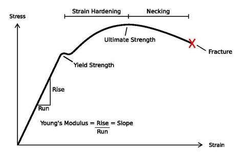
- It is the slope of Stress vs Strain diagram up to Proportional Limit.
- More Young’s modulus means more slope i.e. more close to Y-axis.
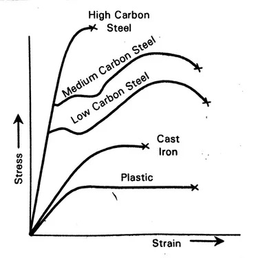
- In the above diagram, the deformation of the High carbon steel is minimum and deformation of the Plastic is maximum.
- Total deformation, (𝛿Total) = Deformation in Elastic Region (𝛿ER) + Deformation in Elastic-Plastic Region (𝛿EPR) + Deformation in Plastic Region (𝛿PR)
𝛿Total = 𝛿ER + 𝛿EPR+ 𝛿PR
- In elastic region deformation in Cast Iron is more than Mild Steel.
- But total deformation of Mild Steel is greater than Cast Iron because in Mild Steel deformation in (Plastic Region + Elastic-Plastic Region + Elastic Region ) is more than Cast Iron.
POISSON’s RATIO:
- When an axial force is applied along the longitudinal axis of the bar, the length of the bar will increase, but at the same time its lateral dimensions (i.e. either the width and breadth or the diameter) will be decreased.
- Thus any direct shear stress produces a strain in its own direction (i.e. Longitudinal Strain) and an opposite kind of strain (i.e. Lateral Strain) in every direction at right angle to this.
- The ratio of the Lateral Strain to Longitudinal Strain is constant for a given material. This constant is known as Poisson’s Ratio.
μ = [frac up=”1″ down=”m”] = [frac up=”(-)Lateral Strain” down=”Longitudinal Strain”] = [frac up=”(-)εy” down=”εx“] = [frac up=”(-)εz” down=”εx“]
Lateral Strain = (-) μ x Longitudinal Strain
- When μ is 0 than Lateral Strain will be zero.
- Cork is the example of such a material in which the μ is zero.
- To prevent the leakage of liquid from the bottle, cork is used because when the liquid exerts pressure on the cork, longitudinal strain will be there but lateral strain of the cork is zero. Therefore, the diameter of the cork will not decrease even after longitudinal strain is there.
- Value of the Poisson’s ratio is same in tension and compression.
|
MATERIAL |
POISSON’s RATIO (μ) |
|
Cork |
0 |
|
Concrete |
0.1 to 0.2 |
|
Metals |
[frac up=”1″ down=”4″] to [frac up=”1″ down=”3″] |
|
Rubber, Wax, Paraffin |
0.5 |
SHEAR MODULUS:
Under bi-axial state of stress, as per Hooke’s law up to the proportional limit.
Shear Stress ∝ Shear Strain
Shear Stress = G . Shear Strain
G = [frac up=”Shear Stress” down=”Shear Strain”] = [frac up=”τ” down=”γ”]
- Consider a small block ABCD in which a shear stress is distributed uniformly over the top face. Then in order for the element to be in equilibrium in the x-direction, an equal but oppositely directed shear stress must also act on the bottom face.
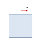
- These two shear stress forms a couple having a moment about he z-axis and have a tendency to rotate the block in the clockwise direction.
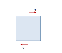
- Equilibrium of the element requires that this moment be balanced by an equal and opposite moment resulting from shear stress acting on the side faces of the element.
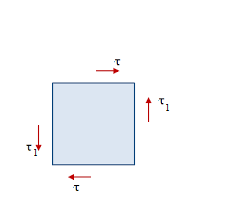
- Denoting the stresses on the side faces as τ1, we see that the vertical shear stress forms a counter-clockwise couple of moment.
- From moment equilibrium τ1 = τ and hence magnitude of the shear stress on the four faces of the element are equal.
- Shear stresses on opposite faces of an element are equal in magnitude and opposite in direction.
- Shear stresses on perpendicular faces of an element are equal in magnitude and have directions such tat both stresses point toward or both point away from the line of intersection.
- τ1 is known as the complimentary shear stress.
- A shear stress in a given direction cannot exist without a balancing shear stress or equal magnitude in a direction at right angles to it.
SHEAR STRAIN:
- Shear strain is defined as the change in initial right angle between the two line elements which are parallel to x and y axis.
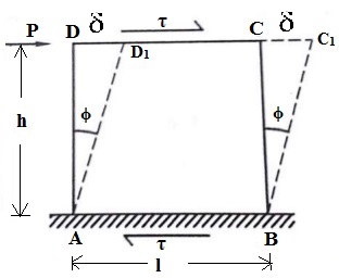
Shear Strain = Shear Angle
γ = Φ
δ = By how much distance the point D and C slides.
In triangle ADD1
tan Φ = [frac up=”δ” down=”h”]
for smaller angles, tan Φ = Φ
Φ = [frac up=”δ” down=”h”]
BULK MODULUS:
- Under Hydrostatic state of stress conditions (Triaxial).
(σx = σy = σz = σ and τxy = τyz = τzx = 0)
Up to proportional limit
Normal or Hydrostatic Stress ∝ Volumetric Strain
Normal or Hydrostatic Stress = K . Volumetric Strain
K = [frac up=”Normal or Hydrostatic Stress” down=”Volumetric Strain”] = [frac up=”σ” down=”ε”]
RELATIONSHIP BETWEEN ELASTIC CONSTANTS:
E = 2G (1 + μ) or G = [frac up=”E” down=”2″] x [frac up=”1″ down=”(1 + μ)”] – (equation 1)
E = 3K (1 – 2μ) or K = [frac up=”E” down=”3″] x [frac up=”1″ down=”(1 – 2μ)”] – (equation 2)
From equations 1 and 2
E = [frac up=”9KG” down=”3K + G”]
E, K, G > 0
μ ≥ 0
From equation 2
If K should become positive
1 – 2μ ≥ 0
μ ≤ [frac up=”1″ down=”2″]
0 ≤ μ ≤ – [frac up=”1″ down=”2″]
UPPER AND LOWER LIMITS FOR G AND K IN TERMS OF E:
| μ | G | K |
| 0 | [frac up=”E” down=”2″] | [frac up=”E” down=”3″] |
| 0.5 | [frac up=”E” down=”3″] | ∞ |
If μ is increased then G will decrease and K will increase
[frac up=”E” down=”3″] ≤ G ≤ [frac up=”E” down=”2″]
[frac up=”E” down=”3″] ≤ G ≤ ∞
For mostly materials μ = 0.3
For More Information:- CLICK HERE
