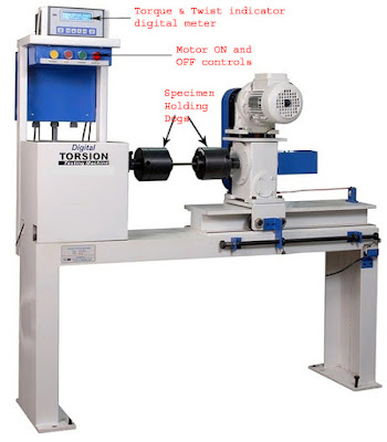
EXPERIMENT
OBJECTIVE:
To conduct torsion test on mild steel specimen to find modulus of rigidity or to find angle of twist of the materials.
APPARATUS REQUIRED:
- A torsion testing machine.
- Standard specimen of mild steel or cast iron.
- Steel rule.
- Twist meter for measuring angles of twist.
- Vernier caliper or a micrometer.
THEORY:
For transmitting power through a rotating shaft it is necessary to apply a turning force. The force is applied tangentially and in the plane of transverse cross section. The torque or twisting moment may be calculated by multiplying two opposite turning moments. It is said to be in pure torsion and it will exhibit the tendency of shearing off at every cross section which is perpendicular to the longitudinal axis.

A torsion test is quite instrumental in determining the value of modulus of rigidity of a metallic specimen. The value of modulus of rigidity can be found out through observations made during the experiment by using the torsion equation.
[frac up=”T” down=”Ip“] = [frac up=”C . θ” down=”l”] = [frac up=”τ” down=”R”]
where,
T= Torque applied
Ip = Polar moment of inertia
C = Modulus of rigidity
θ = Angle of twist (radians)
l = Gauge length
In the testing machine the ends of the specimen are held in suitable grips through one of which the torque is applied; other is connected to the torque arm, by means of which the torque on the specimen is measured. The torque arm is attached to the indicating unit through intermediate levers housed in the cabinet. The levers are so arranged that the load indicator moves in clockwise direction, irrespective of the direction of torsion in the specimen. The char range is selected by means of a hand lever at the front of the cabinet, identical face plates, provided with attachment holes and a tenon slot are fitted to the straining spindle and torque arm spindle. The angular movement of the straining spindle and holder is indicated on a larger diameter protractor and vernier which record deflection down to 0.1 degree.
PROCEDURE:
- Select the driving dogs to suit the size of the specimen and clamp it in the machine by adjusting the length of the specimen by means of a sliding spindle.
- Measure the diameter at about the three places and take average value.
- Choose the appropriate loading range depending upon specimen.
- Set the maximum load pointer to zero.
- Set the protector to zero for convenience and clamp it by means of knurled screw.
- Carry out straining by rotating the hand wheel or by switching on the motor.
- Load the members in suitable increments, observe and record strain reading.
- Continue till failure of the specimen.
- Calculate the modulus of rigidity C by using the torsion equation.
- Plot the torque –twist graph (T vs θ).
OBSERVATIONS:
Gauge length of the specimen, l = ……
Diameter of the specimen, d = ……
Polar moment of inertia, Ip = ……
Modulus of rigidity, C = ……
OBSERVATION TABLE:
| Torque (T) | 1 | 2 | 3 | 4 | 5 | 6 | 7 | 8 | 9 | 10 | 11 | 12 | 13 | 14 | 15 |
| Angle of Twist (θ) ‘in radians’ |
PRECAUTIONS:
- The specimen should be prepared in proper dimensions.
- The specimen should be properly to get between the jaws.
- Take reading carefully.
- After breaking specimen stop to machine.
RELATED VIDEOS:
