STRESS STRAIN CURVE:
The relationship between the stress and strain that a particular material displays is known as that particular material’s stress strain curve.

- The mechanical properties of a material are determined in the laboratory by performing test on the small specimens of the material.
- Most common material test is the Tension Test.
- In this test, loads are measured on the main dial of the machine while the elongations are measured with the help of extensometers.
- It consists of a cylindrical specimen having a diameter of 0.5 inches (12.7 mm) and a gauge length of 2 inches (50.8 mm) between the gauge marks, which are the points where the extensometer arms are attached to the specimen. The cylindrical specimen has enlarged ends so that they can fit in the drips of the machine. This ensures that failure will occur in the central uniform region where the stress is easy to be calculated rather than at or near ends where the stress distribution is not uniform.

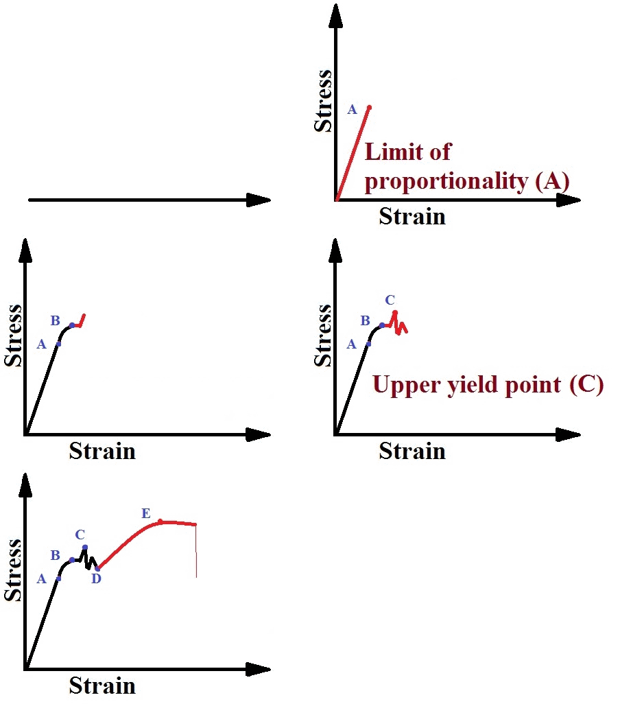
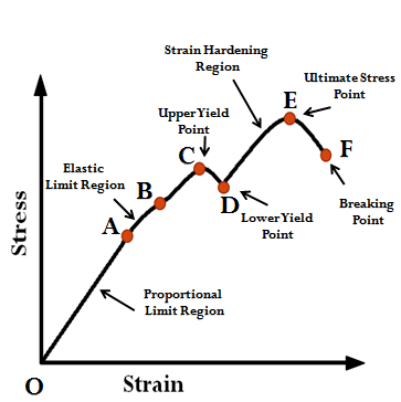
- In this stress strain curve, strain is plotted along the horizontal axis while the stress is plotted on the vertical axis.
O to A:
- In this region, the stress and strain are directly proportional to teach other and the behavior of the material is said to be linear.
A to B:
- Beyond point A, the linear relationship between stress and strain no longer exist. Hence, the stress at A is called the PROPRTIONAL LIMIT or LIMIT OR PROPORTIONALITY. Beyond this, the curve becomes slightly curved until point B is reached.
- With and increase in the load beyond the proportional limit, the strain begins to increase more rapidly for each increment in stress. The stress-strain curve then has a smaller slope until point B the curve becomes horizontal.
- However, up to the point B, the removal of the load would result in complete recovery by the specimen of its original dimensions.
B to C & C to D:
- Point B is the elastic limit of the material.
- Beginning at this point, considerable elongation occurs, with no noticeable increase in the tensile force. This phenomenon is known as YIELDING of the material.
- Stress at point C is called the YIELD STRESS or YIELD POINT.
- In this region, the material becomes perfectly plastic which means that it can deform without an increase in the applied load.
- The strains increasing at an accelerating rate is represented by C to D.
- The elongation of mild steel specimen in this region is 10 to 15 times the elongation that occurs between the onset of loading and the proportional limit.
- Extension in this region is known as DUCTILE EXTENSIONS.
D to E:
- After undergoing the large strains that occur during the yielding in the region C to D, the steel begins to strain harden.
- During strain hardening, the material undergoes change in its atomic and crystalline structure resulting in increased resistance of the material to further deformation. Thus, additional elongation requires an increase in the tensile load and the stress-strain curve has a positive slope form D to E.
- The load eventually reaches its maximum values and the corresponding stress is called the ULTIMATE STRESS.
E to F:
- Up to the maximum load, the bar extends uniformly over its parallel length but if straining is continued, a local reduction in cross-sectional area occurs.
- Further stretching of the bar is actually accomplished by a reduction in the load and fracture finally occurs at a point such as F.
LIMIT OF PROPORTIONALITY:
- It is the stress at which the stress-strain curve ceases to be a straight line.
- It is important because all subsequent theory involving the behavior of elastic bodies is based on stress-strain proportionality.
ELASTIC LIMIT:
- It is that point in the stress-strain curve up to which the material remains elastic i.e. the material regains its original shape after the removal of the load.
- For many materials, elastic limit and proportional limit are almost numerically the same and the terms are sometimes used synonymously. When the two are different, elastic limit is always greater than proportional limit.
YIELD POINT:
- It is the point just beyond the elastic limit, at which the specimen undergoes an appreciable increase in length without further increase in load.
- Yielding is more peculiar to structural steel, other materials do not posses well defined yield point.
- Careful testing of more ductile materials (like annealed low carbon steel) indicates that there is, a slight load reduction giving two yields points known as Upper and Lower yield points.
YIELD STRENGTH:
- It is defined as the lowest stress at which extension of the test piece increases without further increase in load.
ULTIMATE STRENGTH:
- Ultimate Strength = [frac up=”Maximum Load” down=”Original Area of Cross-section”]
RUPTURE STRENGTH:
- It is the stress corresponding to failure point of the stress-strain curve.
- For structural steel, it is lower than the ultimate strength. This is so because the rupture stress is computed by dividing the rupture load by original cross-sectional area, while the actual area is very much less because of necking. The actual rupture strength obtained by dividing the rupture load by the cross-sectional area at the time of rupture, is very much higher than the actual ultimate strength.
- Although the rupture strength of the material is considerably higher than the ultimate strength, the ultimate strength is commonly taken as the maximum stress of the material.
PROOF STRESS:
- It is the stress necessary to cause a permanent extension equal to a defined percentage (0.1 to 0.2 %) of gauge length.
- It is the stress at which the stress strain curve departs form a straight line by not more than 0.1 percent of length of the test piece. The material is said to have passed the proof stress test if application of certain load for 15 seconds does not produce more than 0.1 percent elongation.
DUCTILITY of a material is estimated by two methods:
- Percentage Elongation Method.
- Percentage Reduction in Area.
2nd method is considered to be a better measure of ductility, being independent of gauge length.
PERCENTAGE ELONGATION:
Percentage Elongation = [frac up=”Final Length – Original Length” down=”Original Length”] x 100
Percentage Elongation = [frac up=”Lf – Lo” down=”Lo“] x 100
Basically, Percentage elongation is the percentage increase in the length of the gauge length.
Since the elongation is not uniform over the length of the specimen but is concentrated in the region of necking, the percent elongation depends upon the gauge length. Hence it is always essential to mention the gauge length over which percentage elongation is computed.
PERCENTAGE REDUCTION IN AREA:
Percentage Reduction in Area = [frac up=”Original cross-sectional area – Final Area at the fracture section” down=”Original cross-sectional area”] x 100
Percentage Reduction in Area = [frac up=”Ao – Af” down=”Ao“] x 100
It measures the amount of necking that occurs.
For ductile steels, the reduction is about 50%.
From the stress-strain curve it is observed that total elongation of a specimen is equal to the uniform extension and local extension (due to necking).
It is found that the uniform extension taking place during the elastic and plastic range, is proportional to the gauge length, while the local extension is independent of the gauge length. Due to this it becomes essential to specify the gauge length in a tension test otherwise if the gauge length is increased, the effect of local extension would decrease the percentage elongation.
ULTIMATE STRESS:
The maximum load to which a bar is subjected to in a test divided by the original cross-sectional area, gives a normal stress which is known as Ultimate or Maximum Stress. A tensile ultimate stress is called TENACITY.
WORKING STRESS:
- It is the maximum safe stress the material may carry.
- In design, the working stress should be limited to a value note exceeding the proportional limit of the material.
- Working stress is based either on yield point stress or on ultimate strength by dividing these by suitable factor of safety.
For, Ultimate Strength, Working Stress = [frac up=”Ultimate Strength” down=”Factor of Safety”]
For Yielding Stress, Working Stress = [frac up=”Yield Stress” down=”Factor of Safety”]
- For ductile materials having definite yield stress, working stress is based on Yield Strength.
- For brittle materials, where there is not definite yield point, working stress is based on Ultimate Strength of material.
FACTOR OF SAFETY:
The ratio of ultimate stress to working stress is called factor of safety. It is also known as factor of ignorance. It depends on the following factors:
- Nature of loading.
- Frequency of variation of load.
- Degree of reliability required.
- Decrease of section by corrosion.
Factor of safety is decided by experience.
RELATED VIDEOS FOR STRESS STRAIN DIAGRAM:
