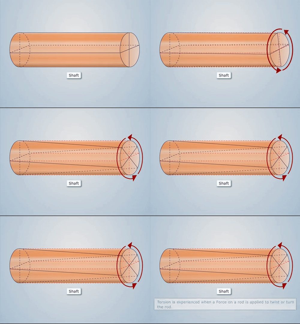
SHAFTS:
The shafts are usually cylindrical in section, solid or hollow. They are made of mild steel, alloy steel and copper alloys.
Shafts may be subjected to the following loads:
- Torsional Load
- Bending Load
- Axial Load
- Combination of above three loads.
TORSION OF SHAFTS:
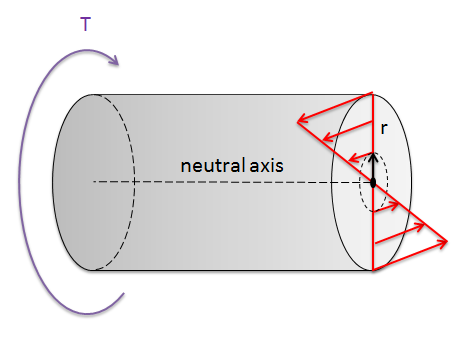
- In workshops and factories, a turning force is always applied to transmit energy by rotation. This turning force is applied either to the rim of a pulley, keyed to the shaft or at any other suitable point at some distance from the axis of the shaft. The product of this turning force and the distance between the point of application of the force and the axis of the shaft is known as torque, turning moment or twisting moment and the shaft is said to be subjected to torsion.

- Shafts are used for transmitting power and in that process, they are subjected to the following torques:
-
- A driving torque at the input end due to power transmitted.
- A resisting torque at the output end, exerted by the driven machinery.
-
- Torsion refers to the twisting of a structural member when it is loaded by couple that produces rotation about its longitudinal axis.
- In this, the moment or couple is applied in a vertical plane perpendicular to the longitudinal axis of a member.
- The couples that produces twisting pf a structural member are called torques, twisting couples of twisting moments.
- A shaft is said to be under pure torsion when it is subjected to two equal and opposite couples in a plane perpendicular to the longitudinal axis of the shaft i.e. twisting couples in such a way that the magnitude of the twisting moment remains constant throughout the length of the shaft.
- Every power transmission shaft is not under pure torsion but a part of a shat is under pure torsion.
TORSION EQUATION:
[frac up=”TR” down=”J”] = [frac up=”τmax” down=”R”] = [frac up=”G . θ” down=”L”]
where,
TR = Maximum Resisting Torque
J = Polar moment of inertia
τmax = Maximum shear stress
R = Radius of the shaft
G = Modulus of rigidity
θ = Angle of twist (radians)
L = Length of the shaft
POLAR MOMENT OF INERTIA:
The moment of inertia of a plane area, with respect to an axis perpendicular to the plane of the figure is called polar moment of inertia.

As per perpendicular axis theorem:
IZZ = IXX + IYY
IZZ = [frac up=”π . D4” down=”64″] + [frac up=”π . D4” down=”64″]
IZZ = J = [frac up=”π . D4” down=”32″]
Polar moment of inertia, J = [frac up=”π . D4” down=”32″]
The torsion equation is based on the following assumption:
- The material of the shaft is uniform throughout.
- Shaft is loaded with twisting couples in planes that are perpendicular to the axis of the shaft.
- The shat circular in section remains circular after loading.
- A plain section of shaft normal to its axis before loading remains plane after the torques have been applied.
- The twist along the length of the shaft is uniform throughout.
- The distance between any two normal cross-sections remains the same after the application of torque.
- Maximum shear stress induced in the shaft due to the application of torque does not exceed its elastic limit value.
- Stress is proportional to strain.
- Material is homogenous and isotropic.
RELATED VIDEOS:
